Table of Contents
**Project 1: Capacitive Piano**
**Introduction**
By using our acquired knowledge from the Embedded Systems course, we decided to use the Arduino Uno microcontroller to create a capacitive touch keyboard piano. By connecting a resistor to aluminum foil, a touch sensing key is created that can measure the electrical capacitance of a person’s body. Seeing as aluminum is conductive, our body’s natural capacitance is capable of releasing a voltage gain through the foil and onto the resistor. The measurement received from the foil will change as the user gets closer and will dramatically spike when the user touches it. The Arduino is programmed to detect these spikes in order to understand when the user has pressed a key. For data transmission onto the microcontroller, we used 8 digital pins connecting the input of the foil, one pin as a common send pin and a final digital pin for the buzzer. The software component takes advantage of Arduino’s CapacitiveSensor library, which turns Arduino pins into capacitive sensors. By programming each key to generate a unique frequency, we can play different tones out of the Piezo buzzer. In conclusion, we were able to create an embedded system for a capacitive touch piano using the tools and knowledge acquired from the embedded systems course.
**Hardware**
Parts
- Arduino Uno microcontroller - Eight 2 MΩ resistors - Piezo buzzer - Jumper cables - Electrical tape - Aluminum foil - Scotch tape - Clip board
Diagram of System
Explanation of Design
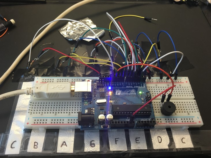
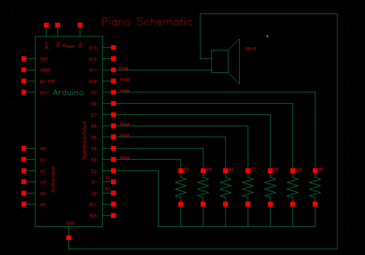
In this design we utilized the Arduino Uno microcontroller. We connected eight resistors to eight pieces of aluminum and then soldered two jumper cables to each end of each resistor. We then took the jumper connected to the end of each resistor touching the aluminum and placed the end inside one of the digital pins of the Arduino. This way we connected the resistors to pins D3- D10 using the jumper cables. Next, we connected the all the jumpers on the side of the resistor not connected to the foil, to a common rail on the bread board and then connected that rail using a jumper to pin D2. Next, in order to generate sound on the system we connected a Piezo buzzer to pin D11 and to ground. Finally, we taped down all the aluminum foil onto a clipboard using electrical tape and then scotch tape directly over all the notes to keep them in place. For the choice of resistors, we chose a 2 MΩ so that the touch sensor is not overly sensitive to change.
Physics Explanation The way the Arduino senses capacitance is it uses a simple RC circuit between two pins. In our case one of them was between digital pin 2 and digital pin 3. Using a large resistor like 2MOhms, we limit the current with which the “capacitor” will be charged. There is no actual capacitor connected to the circuit but the aluminum foil has an inherent capacitance. When digital pin 2 changes its state, this change is observed at the digital pin 3. The charge needs to move onto the aluminum foil, in order for pin 3 to detect this voltage change. Since we have a small current provided by pin 2, this takes an observable amount of time. A larger capacitance means that the aluminum strip can hold more charge thus a longer delay until the change is detected. The Arduino’s CapacitiveSense library uses a for loop to increment a variable until pin 3 detects the change. The value of this variable depends on how long the delay was.
**Software**
Code Import the CapacitiveSensor Library. #include <CapacitiveSensor.h> Name the pin as led. #define speaker 11
Set the Send Pin & Receive Pin. CapacitiveSensor cs_2_3 = CapacitiveSensor(2,3); 10M resistor between pins 4 & 2, pin 2 is sensor pin, add a wire and or foil if desired CapacitiveSensor cs_2_4 = CapacitiveSensor(2,4); 10M resistor between pins 4 & 6, pin 6 is sensor pin, add a wire and or foil CapacitiveSensor cs_2_5 = CapacitiveSensor(2,5); 10M resistor between pins 4 & 8, pin 8 is sensor pin, add a wire and or foil CapacitiveSensor cs_2_6 = CapacitiveSensor(2,6); 10M resistor between pins 4 & 8, pin 8 is sensor pin, add a wire and or foil CapacitiveSensor cs_2_7 = CapacitiveSensor(2,7); 10M resistor between pins 4 & 8, pin 8 is sensor pin, add a wire and or foil CapacitiveSensor cs_2_8 = CapacitiveSensor(2,8); 10M resistor between pins 4 & 8, pin 8 is sensor pin, add a wire and or foil CapacitiveSensor cs_2_9 = CapacitiveSensor(2,9); 10M resistor between pins 4 & 8, pin 8 is sensor pin, add a wire and or foil CapacitiveSensor cs_2_10 = CapacitiveSensor(2,10); 10M resistor between pins 4 & 8, pin 8 is sensor pin, add a wire and or foil void setup() { cs_2_3.set_CS_AutocaL_Millis(0xFFFFFFFF); turn off autocalibrate on channel 1 - just as an example
    // Arduino start communicate with computer.
    Serial.begin(9600);
}
void loop() {
    // Set a timer.
    long start = millis();

    // Set the sensitivity of the sensors.
    long total1 =  cs_2_3.capacitiveSensor(60);
    long total2 =  cs_2_4.capacitiveSensor(60);
    long total3 =  cs_2_5.capacitiveSensor(60);
    long total4 =  cs_2_6.capacitiveSensor(60);
    long total5 =  cs_2_7.capacitiveSensor(60);
    long total6 =  cs_2_8.capacitiveSensor(60);
    long total7 =  cs_2_9.capacitiveSensor(60);
    long total8 =  cs_2_10.capacitiveSensor(60);

    Serial.print(millis() - start);        // check on performance in milliseconds
    Serial.print("\t");                    // tab character for debug windown spacing

    Serial.print(total1);                  // print sensor output 1
    Serial.print("\t");                    // Leave some space before print the next output
    Serial.print(total2);                  // print sensor output 2
    Serial.print("\t");                    // Leave some space before print the next output
    Serial.print(total3);                  // print sensor output 3
    Serial.print("\t");                    // Leave some space before print the next output
    Serial.print(total4);                  // print sensor output 4
    Serial.print("\t");                    // Leave some space before print the next output
    Serial.print(total5);                  // print sensor output 5
    Serial.print("\t");                    // Leave some space before print the next output
    Serial.print(total6);                  // print sensor output 6
    Serial.print("\t");                    // Leave some space before print the next output
    Serial.println(total7);                // print sensor output 7
    Serial.print("\t");                    // Leave some space before print the next output
    Serial.println(total8);                // print sensor output 8

                                           // "println" - "ln" represent as "line", system will jump to next line after print the output.

    // When hand touches the sensor, the speaker will produce a tone.
    // I set a threshold for it, so that the sensor won't be too sensitive.
    if (total1 > 150) tone(speaker,523); // Low C
    if (total2 > 150) tone(speaker,587); // D
    if (total3 > 150) tone(speaker,622); // E
    if (total4 > 150) tone(speaker,698); // F
    if (total5 > 150) tone(speaker,784); // G
    if (total6 > 150) tone(speaker,880); // A
    if (total7 > 150) tone(speaker,988); // B
    if (total8 > 150) tone(speaker,1047); // High C

    // When hand didn't touch on it, no tone is produced.
    if (total1<=150  &  total2<=150  &  total3<=150 & total4<=150  &  total5<=150  &  total6<=150 &  total7<=150 & total8 <= 150)
      noTone(speaker);

    delay(0);                             // arbitrary delay to limit data to serial port
}
**Code Explanation**
For this project we took advantage of Arduino’s CapacitiveSensor library that can turn the board’s pins into capacitive sensors by detecting the electrical capacitance of the human body. The sensor needs a medium to high value resistor, a piece of wire and a piece of aluminum foil on the end. The library works by toggling the microcontroller send pin to a new state and then waiting for the receive pin to change to the same state as the send pin.
In order to take advantage of the library we create an instance of the library using the constructor CapacitiveSensor(byte sendPin, byte receivePin). We create eight instances of the library for all eight keys and have a shared send pin, as well as a unique receive pin for each key. Next, in the setup function we call the function set_CS_AutocaL_Millis() in order to turn off autocalibation for the timeout interval of the capacitiveSensor function. Next, in the loop function we create a long value called totali (depending on the i) and set it equal to the result of calling the capacitiveSensor(60) function. This function takes the amount of samples and returns a long containing the added (sensed) capacitance, in arbitrary units, by keeping track of the lowest baseline (unsensed) capacitance and subtracting that from the sensed capacitance. Next, we print the results of each capacitance with a tab separator in between so we know which key is being pressed and the value of the capacitance that is being measured. Finally, we play a tone when the hand touches the sensor as long as the totali value is greater than a threshold value of 150, if the value is less than or equal to 150 then no tone is played. This all exists in a loop, so the user can continue to play keys forever and the Arduino will continue to print the results.
**Conclusion**
In this project we wanted to demonstrate the knowledge we acquired from this class and several other classes to design a simple embedded system that performs a specific task. The task involves direct user interaction with the interface (finger contact with the piano keys). In this case our Capacitive-Sensitive piano uses the signal from this interaction to initiate a reaction in the form of sound.
We applied all the critical ideas from knowing how the microcontroller works to knowing how it communicates with other devices. There was a software consideration since it is one of the key steps in the design of an embedded system. Our choice of the arduino was simply because it is easy to use and it comes with a well equipped library as well as numerous online resources. We also considered the level of user interaction required for the piano to work and the amount of delay each signal requires in order to avoid noise interference with other keys.
Overall, it was a good learning opportunity for us to design this simple but functional capacitive sensitive piano in order to fully demonstrate our knowledge of the course. The parts were easy to find and we enjoyed every minute of the design process.


