Table of Contents
Group 1 (Trackingineers)
Distributed Camera Surveillance Network for Multi-Object Tracking
Students: Varun Kalia, Raiyan Awal, Tayo Kadiri, Manfred Adan Lopez
Project Adviser: Professor Amir Asif
Mentor: Arash Mohammadi
Course Director: Professor Ebrahim Ghafar-Zadeh
Project Video
Team Members
Background & Motivation
Multi-camera networks are increasingly being deployed recently on a large scale in a wide range of applications including surveillance, security, disaster response, and activity recognition. The existing state of the art technology involves storing and analyzing the captured video streams at a fusion center, which is central to the video surveillance networks. Such a setup is not conducive due to latency introduced on account of transferring streams to the fusion center. Another challenge is introduced due to manual handling of the separate streams, which undermines the potential of such networks. This necessitates the need for development of distributed camera networks, which dynamically use reconfiguration and consensus algorithms to allow for refined estimates of object tracks.
Project Summary
In our project, we automate the current technology in hardware in a cost efficient manner to provide the end user with greater flexibility. Specifically, we address the surveillance problem of tracking a target over a network of video cameras with partial overlaps in their coverage areas. We focus on decentralized, non-linear estimation/tracking algorithms in distributed camera networks, where a group of spatially distributed camera nodes observe a dynamical environment with the objective of estimating/tracking moving targets cooperatively without the need of a fusion center.
Design Overview
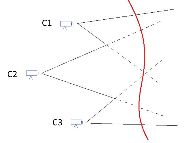
Our objective is to track a target from the field of view of 2 camera nodes and gather local estimates which are then shared among the different cameras in the network in a gossip-type fashion to compute a global consensus of a scene depending upon the location of target at a given instance of time.
The target must appear in atleast both camera nodes for to allow for parameter estimation.
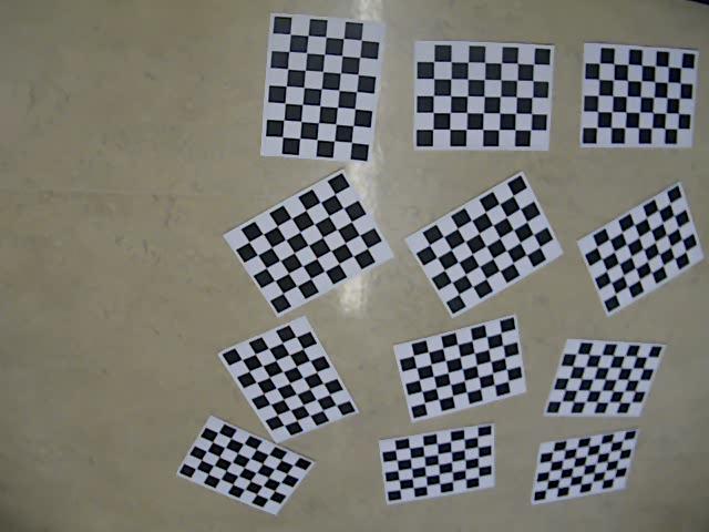
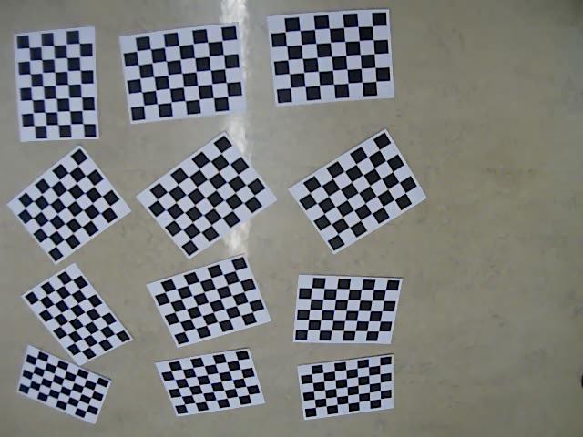
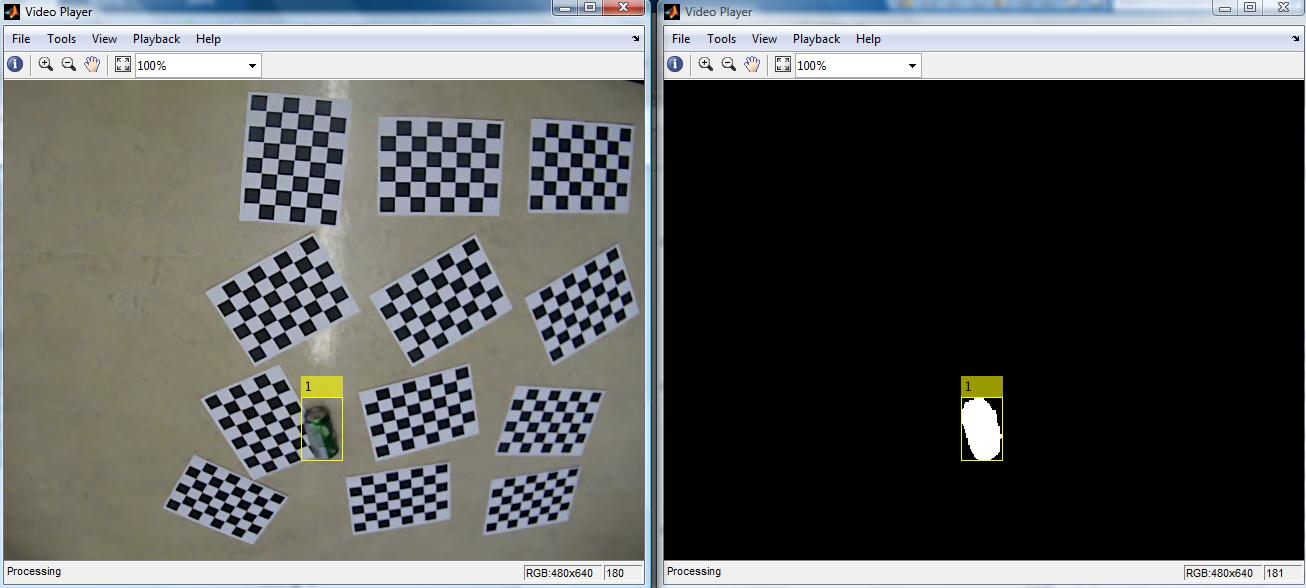
We created a simulation environment with 2 cameras: Camera 1 and Camera 2. The cameras were calibrated to create an overlapping field of view to ensure that the object appears in both cameras. In order to find maximum point correspondences to reconstruct the global scene, we inserted patterned objects in the monitored area. As soon as the target is detected in a camera, it is constantly analysed using blob analysis technique coupled with background subtraction wherein the object is seen as a white entity and the rest is black. The object's trajectory is simultaneously calculated and eventually fused for the global reference frame.
Offline Simulation
After performing the controlled experiment where we had most of the aspects known to use such as less coverage area, the speed of the object, maximum overlap between camera nodes and least amount of shadows we turned to a more realistic environment. The conditions were drastically different in that the coverage area was widened to account for the height of a human thereby causing us to place constraint on the installation height of the cameras. Unlike a can, we now had no control over the velocity of the target in question. The following figures attest to our capability in overcoming many changes in a scene and maintaining our objective.
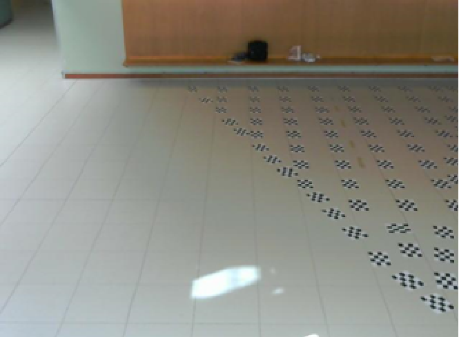
Camera 1 Field of view Area monitored by Camera 1: As visible, we inserted the checkerboard-like patterned objects in the view so as to obtain a common set of points in order to come up with a global view.
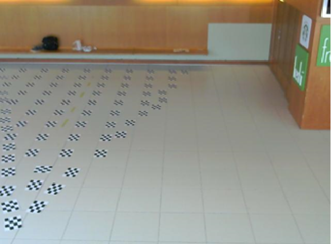
Camera 2 Field of view Area monitored by Camera 2: As visible, we inserted the checkerboard-like patterned objects in the view so as to obtain a common set of points in order to come up with a global view.
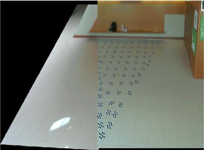
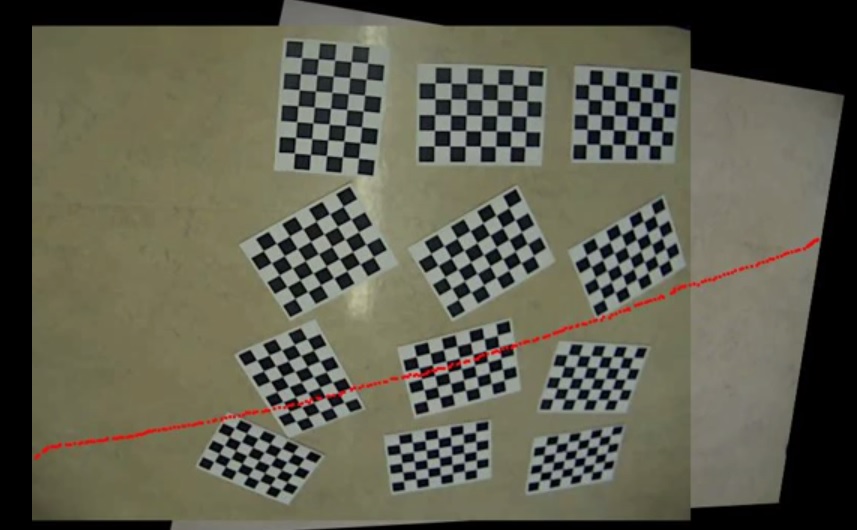
Global view The global view is obtained using point correspondences and is almost a 100% match with no irregularities. Visually, the image from Camera 1 appears to be accommodating the image from Camera 2. This is so because instead of creating a new reference frame and modifying both data set points for a completely new coordinate system, we reduced the processing time here by assuming the image from camera 2 as a reference in itself.
Snapshots from a simulation when algorithm was run
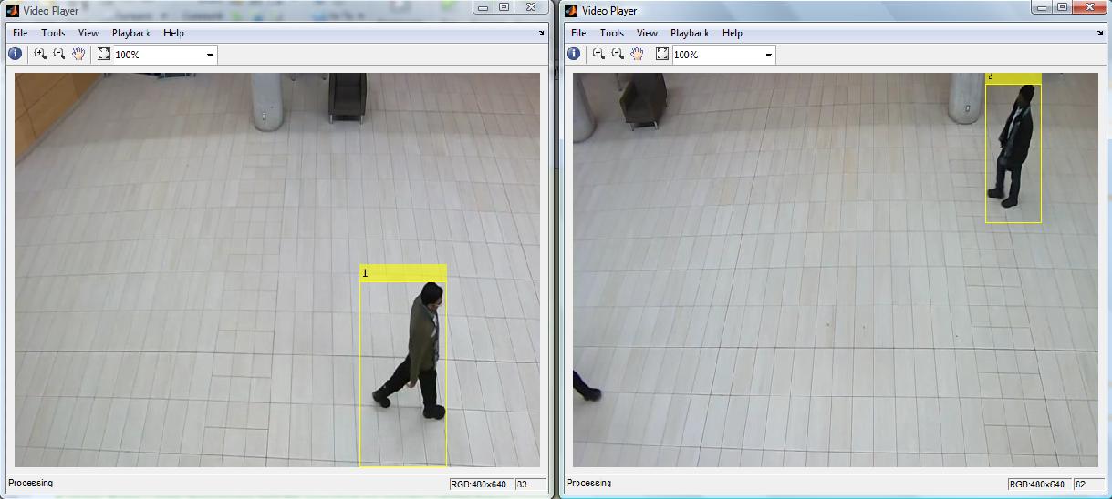
The image below from another simulation shows two moving targets being tracked in different views. Note that the track ID's for both targets are unique i.e 1 and 2. Also, the targets initially appear in different cameras.
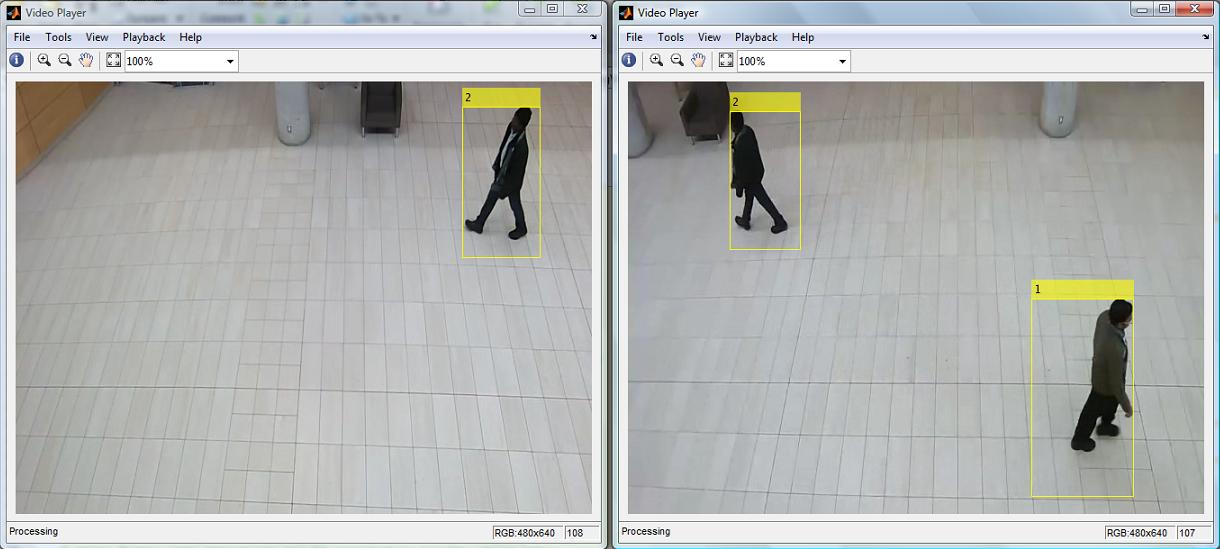
The following image shows when a target crosses over and enters the field of view of another camera. Note that the track ID of the target is the same as the target now appears in the field of view of both cameras.
Achieved Results
Our results and findings closely matched our expectations:
- Successfully identified and tracked a moving target in a single camera view with limited influence of external noise i.e. shadows.
- Kept track of the chosen target even if 2 or more targets are close to one another at any time
- Extended the algorithm to handle multiple camera views without losing important information
- Created global reference frame which merges two different camera views resulting in flexibility for the end user
- Transition of targets into different views are smooth and lag-free
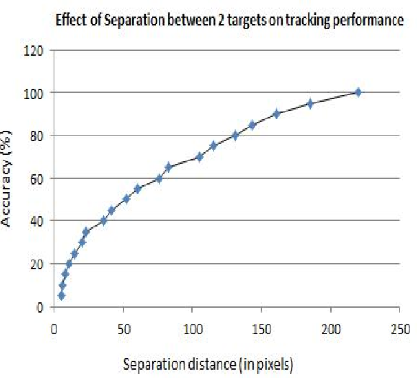
We also found out that the more the spatial distance between two targets, the higher is our accuracy in detecting and tracking the same target. If the two targets are in close proximity of each other, the accuracy with which we distinguish the targets from one another reduces. The following graph represents these observations:
Controlled Experiment and Results
Camera 1 Field of view Area monitored by Camera 1:
Camera 2 Field of view Area monitored by Camera 2:
Blob Analysis Analyzing the object of interest via background subtraction
Global view Reconstructing the global reference frame to represent the global track of the object from Camera 1 and Camera 2
Novelty of our solution
We were successfully able to identify a moving target in two different views with a relatively high degree of accuracy. The tracking approach in our project is independent of color. Furthermore, we have extended the functionality of our design to a dynamic live environment.
Marketability
Our approach can be adapted to meet the needs of commercial applications.
Engineering Design Approach
An engineering design can be divided into five stages – Requirement, Design, Implementation, Testing and Maintenance. We have adopted all of these stages as below:
- Requirement: We discussed the project specifications with our adviser and mentor and made sure we understood the main requirement of our project. To that end, we also created a proposal document.
- Design: We thoroughly researched about possible design methodologies that we could make. We weighed various options and chose the one that was both academically and financially suitable for us.
- Implementation: Based on the design, we first created a simple prototype. We continuously enhanced the basic implementation to add features.
- Testing: We took results of different parameters and compared with the actual expectations. Eventually we took the best result to represent our project
- Maintenance: We documented our project and revised our code iteratively to achieve desired results.
Design Complexity
We had a quite a complicated design. We needed to maintain an overlap between camera nodes so as to cover wide areas. Every time we carried out a simulation, we needed to make sure that camera nodes were precisely vertically panned in order to have same height at which the camera nodes were installed initially.
Obtaining an accurate homography from the set of coordinates collected from two views was crucial to obtain an exact global view. To overcome that challenge, we ran the RANSAC algorithm 100 times and took the average to obtain a more accurate matrix.
Future Work
- Improve algorithm to decrease the effect that shadows have on the background subtraction in the blob analysis process
- Increase the accuracy of successful detection from one view to another
- Automate the process of obtaining point correspondences
Industrial Partners
There are no industrial partners for our project however the following companies may have similar interests as us –
- AXIS Communication (http://www.axis.com)
- Aartech Canada (http://www.aartech.ca)
- Cobra Integrated Systems (http://www.cobraintegratedsystems.com)
- Genetech (http://www.genetec.com)


