Table of Contents
Group 3 - VRobotics
VRobotics: botBlocks - A Robotic Development Platform
Students:
- Md Zahed Hossain
- Isaac DeSouza
- Robert Mete
- James Timbreza
- Jookhun M Ishfaaq
Project Adviser:
- Professor Sebastian Magierowski
Mentor(s):
- Giancarlo Ayala
- Goran Basic
Course Director:
- Professor Ebrahim Ghafar-Zadeh
Company website: http://www.vrobotics.ca
Selected as one of the groups for MaRS by Lassonde School of Engineering
About MaRS:
MaRS is where science, technology and social entrepreneurs get the help they need. Where all kinds of people meet to spark new ideas. And where a global reputation for innovation is being earned, one success story at a time.
For more information about MaRS visit this link:
Group Members
Description of Project
VRobotics : BotBlocks
The primary objective of this project is to develop a fully functioning 6 degree-of-freedom (DOF) robotic arm with 1 meter maximum range that is capable of receiving visual cues as well as audio commands to execute pre-programmed functional capabilities. The basic functionality would be to use a pointing device such as a laser pointer, aim at a particular object, and verbally use a command such as “Pick Up” or “Push”. The robotic arm would then perform the action as required. Further functionality would also be explored through the use of capacitive touch sensors, accelerometers, laser scanning, and image recognition software used to construct high level user-interfaces.
Ultimately, the robotic arm would have be able to learn series of actions taught completely through visual and audio commands based on a basic library of movements available to it.
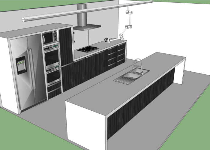
Our target environment is a kitchen where the arm would be suspended from a support and then it would be able to perform some tasks on kitchen utensils. This is one of the many uses, but for simplicity we have chosen this environment.
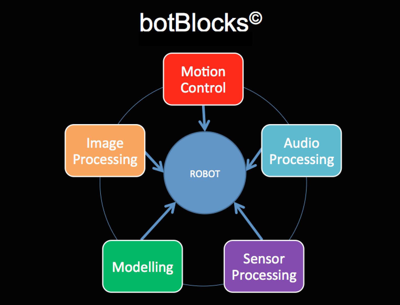
Our project have 5 components:
- Voice recognition (Audio Processing) : VeeVoice
- Sensors and Mapping : VeeCloud
- Computer Vision (Image Processing) : Veesion
- Design and Hardware integration (Motion Control) : ICCE
- Kinematics Model : VeeNverseKinamatics
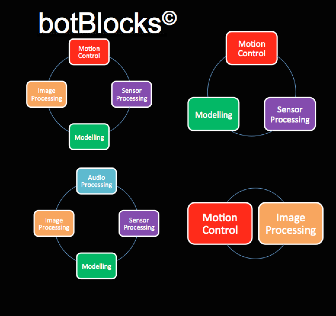
Design and Hardware integration involves the designing of the arm and the require hardware components to control the arm. The other 4 components are involved with the operation of the arm. The chart below shows all our modules and how they can be integrated in different ways for different kinds of applications.
As we can see, these five modules could be used to control a robot.
In the above figure we can see the different configurations of the modules. For example, the ICCE (Motion control) module and the Veesion (Image processing) module could be used to control a robot. On the other hand, with that configuration, we can just add the VeeCloud (Sensors and Mapping) module to add more functionality to the robot. Hence, it is scalable. We can use two of the same module if needed to control different parts of a robot. This is made possible because of the modular design of botBlocks. This makes our design unique and more user friendly.
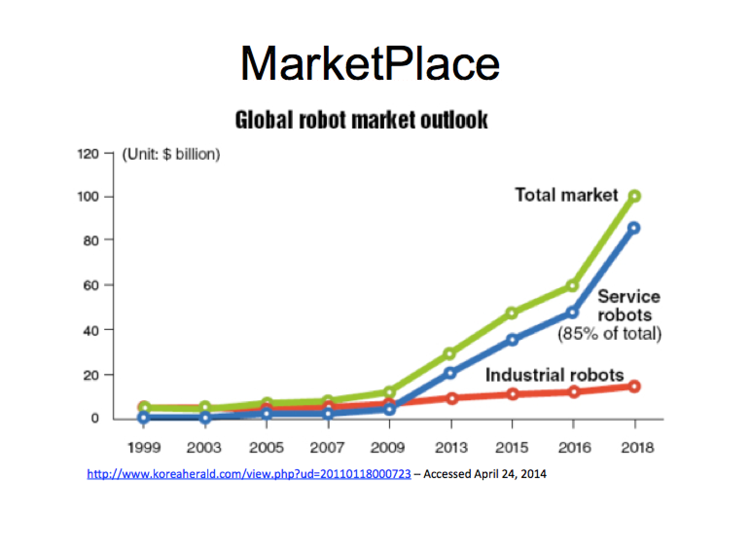
The graph below shows the current trend in the robotic industry. This shows why we have chosen the right field on the right time because the sales of service robots are increasing very rapidly and are projected to increase every year with revenues topping billions.
VRobotics : Design Complexity
Our project has 5 different components, which includes both hardware and software solutions. This makes our project one of the complex designs in the ENG4000 course. We design an arm, of length 1.3 meters, from scratch. We have used development boards that doesn't have a huge community yet and lacks support and software. This contributed to more complexity in terms of installation of software and integration. We have implemented serial communications and devised our own protocol to maximum this communication and to reduce and handle errors. Hence, a lot of time has been spent on each sub-project to make it work. Making our systems reliable was also a challenge since most of these technologies (voice recognition, computer vision, mapping) are still a field of research. We have followed our own approaches to make these systems more accurate and reliable so that systems built using our modules are also reliable.
Brief Description of the Blocks
Each sub-project plays an important role in the development of this robotic platform. Moreover, each sub-project in itself can be used in many other technologies. A brief description of each of the sub-projects and their role in the project is explained below. Some applications of each of these sub-projects are also mentioned to justify that they can be used in many ways.
Voice Recognition and Serial Communication
Voice is the most natural and easiest way of communication because it doesn't need the push of a button like a remote control, for example. We want our platform to be able to interact with its environments as easily as possible and there is no other way of doing it other than voice. Voice controlled system has many advantages, one of which is the ability to easily extend the system to multiple languages without the need to add extra cost to the product. There aren't that many robotic platform that uses the voice technology because it is not that reliable and part of the reason is the use of inexpensive technologies. We are tackling these issues by limiting our recognition space (limiting what can be recognized and what cannot be). This increases the performance of our system drastically because the search space has been truncated down only those that are needed. This means that our system is efficient as well as inexpensive, giving developers the chance to build their own platform using our blocks.
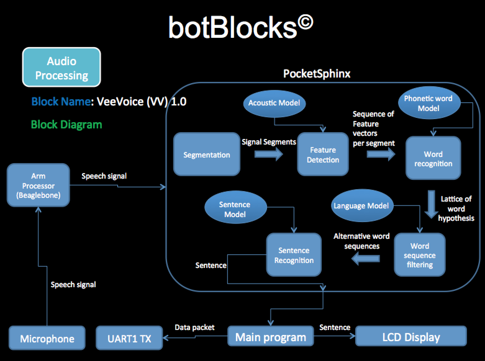
We chose to use voice recognition in our design to initiate a task or a request. The flow chart below shows the over all voice recognition system.
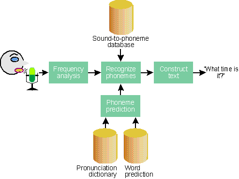
The above flow chart shows how we get the speech data from (from the mic) and what we do with it. We get the speech from the mic, we compare it with our acoustic, language, sentence model, and then we send the data back to our common data bus, which is received by all the other modules. Now, depending on the source and destination, the appropriate module will consume this data. As you can see this is the entry point in our system. The images below shows how voice recognition in general works.
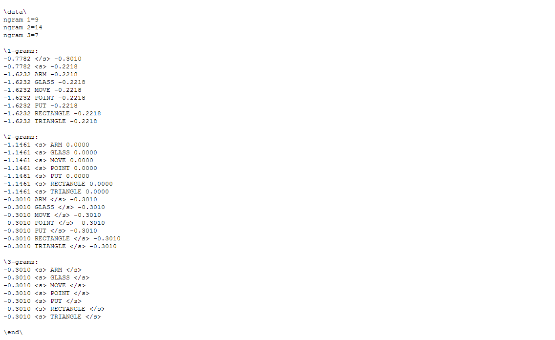
The images illustrates the different stages of the recognition system. It is a complex system, but to sum up, we basically speak using microphone which is captured and processed by the sound engine (pocketsphinx in our case), compared with different models (acoustic models, language model, dictionary model, etc), and then the best match is returned as a complete sentence, which can then be used as needed. The database/acoustic/language models are the key parameters because they decide the performance of the system. Depending on these models and depending on the accent of each individual (the way a person talks) the performance varies. Hence, customization is required for an accepted performance. Customization can be done at many level. Acoustic models can be trained for specific purpose (for example different language). Language and Dictionary model can be trained for small projects that require high performance. We have chosen to use the open source voice recognition engine 'pocketsphinx' that is developed at the Carnegie Melon University (CMU). The reason is that it is lightweight, uses less resources, highly customizable, very efficient and most important of all, it is meant to be used in devices with less resources such as the BeagleBone development board that we are using in our project. We require high performance. Hence, to make the system more efficient we have trained our own language and dictionary model. The result of this is a more robust product with increased efficiency and performance. The images below shows a small part of our language model.
Many different commands (tasks) can be constructed from the vocabulary model shown in the first figure(for example, Arm move, Arm point, Move glass, Put glass, etc). The second figure shows the associated language model for this vocabulary, and the third figure shows the mapping between a word and it's corresponding phoneme. Using these models constraints the voice recognition system to only recognize those sentences that can be constructed from all the possible permutations of the words available in the vocabulary model. Since, there are a few meaningful sentences and each of them sounds different, this elevates the performance and the efficiency of the system, making it the most suitable communication tool for our platform.
This block (module) can be used with other platforms as well. For example, this can be used to automate a house using voice communication, as a universal remote control for all the electronics (television, computer, etc). It can also be integrated into an automobile (such as cars). The applications of this technology are endless.
Vision and Image Processing
Computer Vision is a field that includes methods of acquiring, processing, analyzing and understanding images in real word in order to produce data that the computer understands. We are using computer vision so that the robot arm gains the ability to “see” its environment and process it so that the robot arm can interact with the environment.
There are many techniques to perform computer vision. Color tracking and shape tracking has been chosen because of the nature of its image processing algorithm. They are not very taxing in CPU and RAM resources. But considering that the image processing will run on Beaglebone development board, the CPU and RAM resources will be very limited. Having said that, there are issues that affect the reliability of color and shape tracking algorithms.
Color Tracking suffers from dynamic lighting. The color of an object is affected by the brightness of the room where the object is situated. If the object is not well lit, the darker the color of the object will be. Initially, the project will be situated at a kitchen where the light does not change dramatically. So the only solution to this so far is that the algorithm has to be calibrated properly to the rooms lighting conditions.
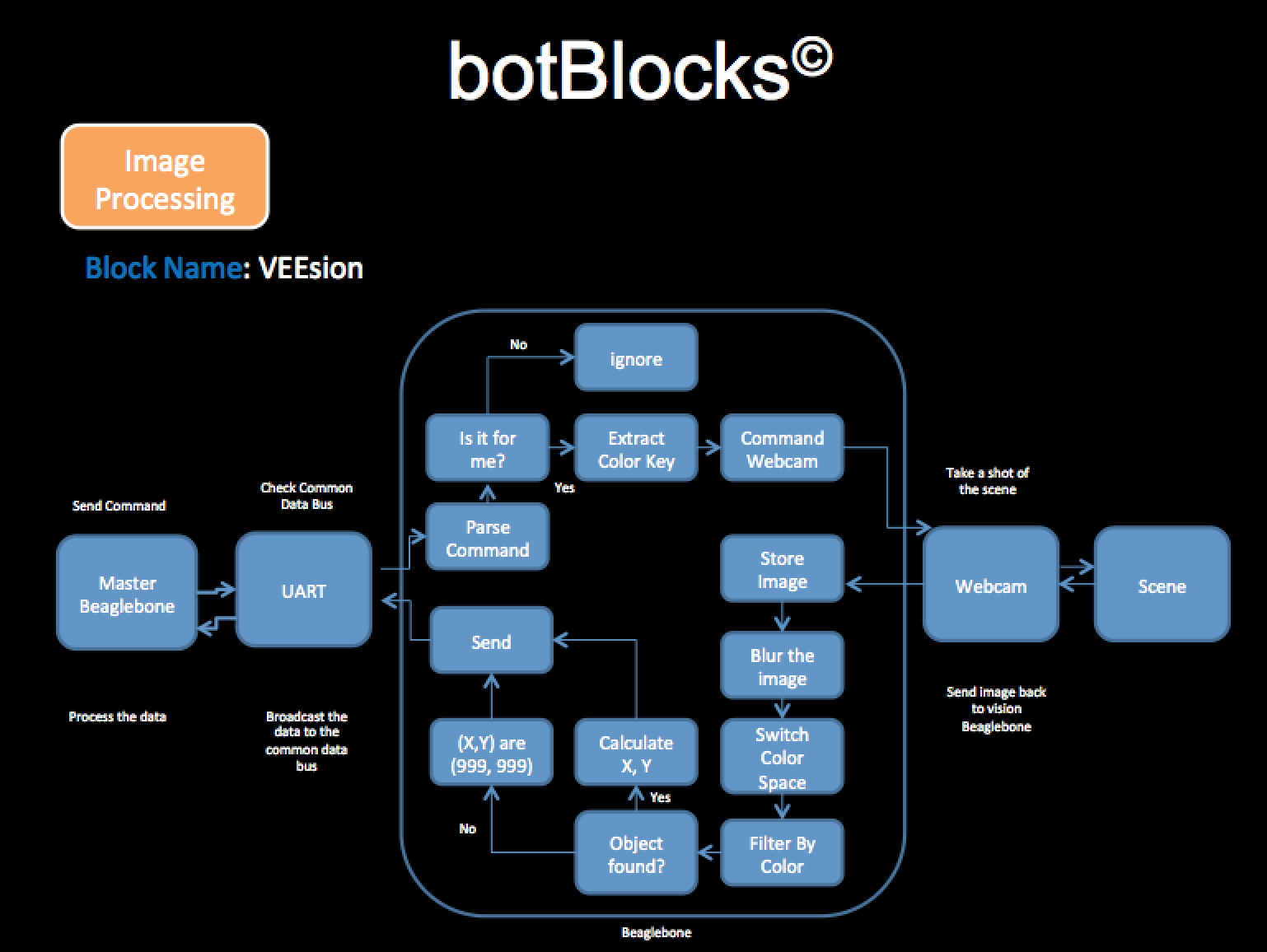
Shape tracking with only one camera produces problematic errors with 3D objects. For instance, a cube viewed on the top looks like a square, but when it is viewed on one of its corner, it looks like a hexagon. The good news is that we only aim to process simple shapes and most of the time, the robotic arm most of the time will view the object at the top. The bad news is that since the design decision that we will only use 1 camera to do computer vision prevents me from doing computer vision in order to process depth. So why did we use only one camera if depth is needed to reach an object? The answer to that is that the computer vision only gives the (x,y) coordinates and the depth will be given by a laser sensor. Therefore, no image processing is done when the robot wants to find how far the object is. The image below shows how our vision module works.
A flow chart below shows how the CV (color vision) algorithms in general work.
The approach I took that sets me different than other image processing technique is that using the more simple algorithms I am order to N objects having N different colors. Using shape tracking, I am able to identify M objects having M different shapes. Combining these two algorithm, I am able to identify NxM different objects with N different colors and M different shapes. But that is not the special part, the special part is I am delegating the acquisition of depth outside the image processing algorithm so that the shape and color algorithm is not as taxing in CPU and RAM resources so that we are able to run these two algorithms on the Beaglebone Black development board.
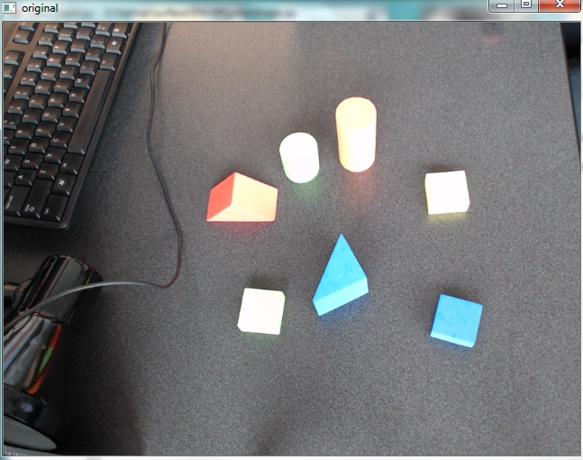
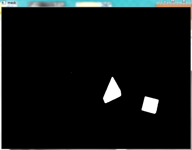
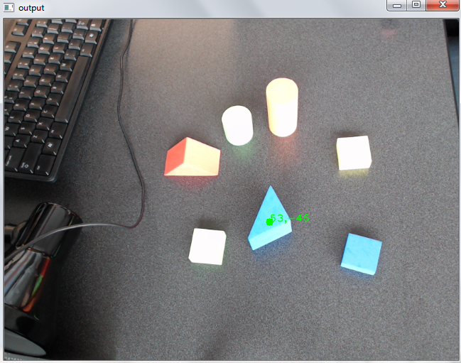
The figures below shows how the camera locates the object and finds its coordinates.
As can be seen, the first figure shows the original image that is seen by the camera. Our algorithm then makes a mask of the image for the object of interest, which is shown in the second figure. Lastly, it uses the algorithm to locate the object's position in the image coordinate system. This coordinate is then sent out to the master block (module) of our design to be used to move to the target position.
Apart from this project, this module could be used in many ways. For example, it could be used to detect the presence of someone inside a room, thereby turning on the light (home automation).
Sensor and Mapping
Computer vision is a field of robotics that is much in need of a new breakthrough. Point cloud based vision systems do offer a great way to gather location data from your surroundings. Combined with a camera, they can be a great asset to any robotics project. One major downside to this system is development time. Development time is long because there isn’t a lot of information out there on how one can create their own system. The worst part is that you can’t even buy a preconfigured system, other than say the Kinect, though the Kinect suffers from range limitations. Imagine how much time it would save you by offloading the development time for this sensor. How about every onboard sensor? See where I’m going with this? One could develop a complete advanced working robot in just weeks. This is what we are now striving to achieve at VRobotics.
Our approach to this problem is to use a cheap low-cost high performance arm platform for processing sensor inputs. Some examples are the Beaglebone Black, Raspberry Pi, etc. In the case of the beaglebone black, you have ample amounts of processing power (1 GHz processor with 512MB Ram), and all for around $50. We will be offering these smart sensor modules (bot block sensors), all for a cost that is only marginally higher than the sensor itself, with the primary benefit of cutting development time.
Unfortunately, the cost of laser range sensors (like the urg-04lx) will be difficult to change with the current market. Some sensors can be upwards of $1500. The way we see it, as a result of Point Cloud processing being more easily accessible, the demand for Range scanners will increase. This will eventually force manufacturers to develop products that are more cost friendly.
What sets our point cloud block apart from the rest is that it is ready to go right out of the box. It uses a serial interface to transmit 3D maps. The brain and all internal processes are hidden out of sight and out of mind…so you can focus on your project.
We are happy to announce that we have achieved our goals. The point cloud system is able to obtain a point cloud, process it, and send it via serial. We are very happy with the results and believe it holds great potential in the world of robotics.
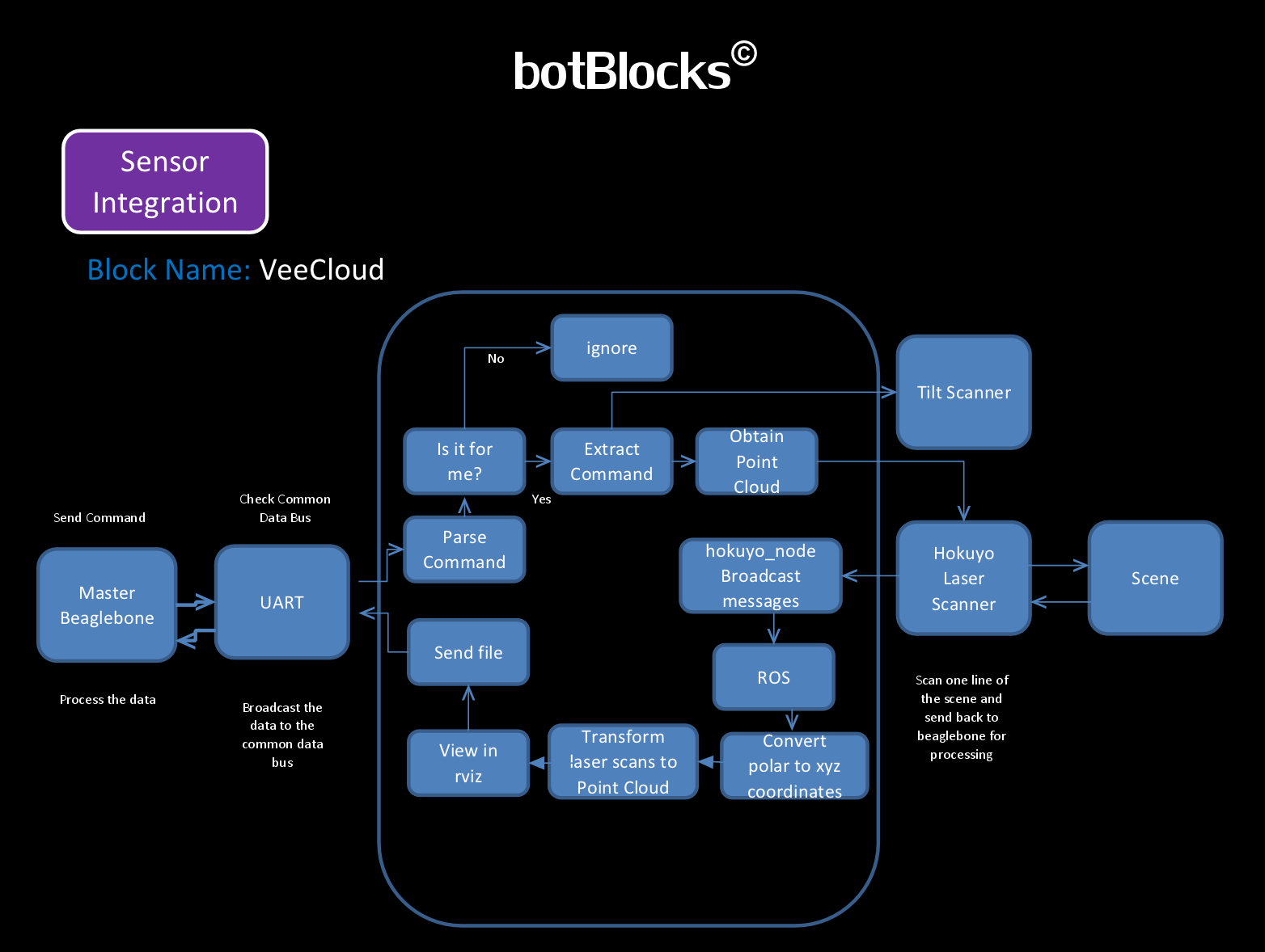
A flow chart of our VeeCloud system is shown below:
Inverse Kinematics and Movement
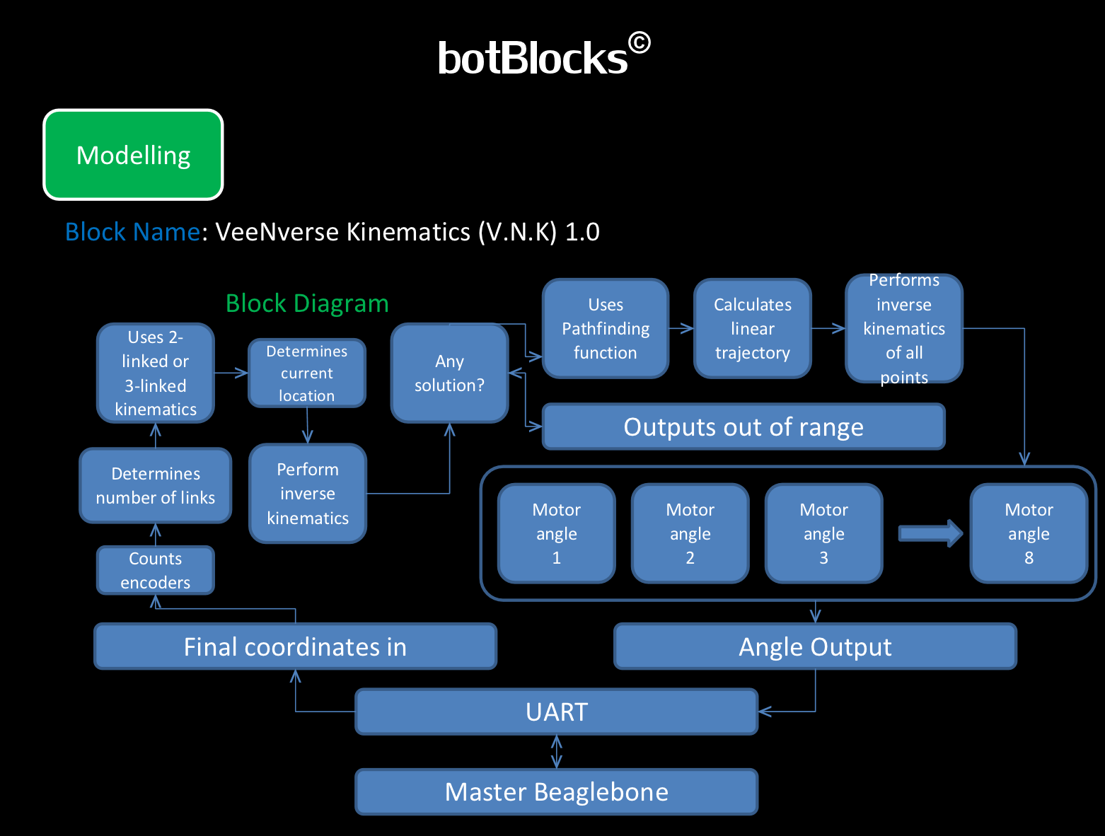
This specific subsystem deals with planning out the motion of the arm not only to make the arm reach its desired destination but also to make sure that the arm does not find itself in compromising situations whereby its movement are going to be hindered. The flow chart for this system is shown below:
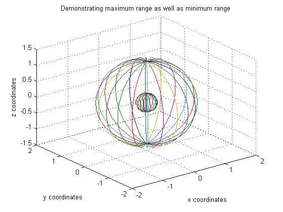
Any robotic platform that requires any form of automated response to a change in its environment will have to have an inverse kinematic system. The challenge posed by our current robotic arm is not only that due to the amount of links it has, there are several configurations to take into account but also since it is a modular robot, at least a significant amount of models have to be considered for any given amount of modules connected. Therefore there is going to be 2 links and 3 links configuration and using the encoders available, we would therefore be able to determine which configuration the arm is in and the arm will know which inverse kinematic set to use. Also collision detection is another aspect being worked on currently and progress is being made when dealing with motion of the arm within the range of the arm itself since there is a region close to the origin whereby the arm cannot reach. Such an example being tackled is when the arm gets too close to the origin of the coordinate frame. In which case points which would then be going through a region inaccessible to the arm in order to get to one which can be accessed, the points whose value are imaginaries are then made to go through the same motion except on the surface of an artificial sphere modelled to make sure to get around this problem.
If we switch the whole frame into a spherical coordinate system, the end effector would go through the same azimuth and zenith angle though the radius in question would change and match that of an artificially created sphere.
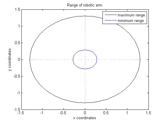
The inverse kinematics is computed using a python script and is cross referenced with MATLAB and Mathematica codes. Some of the results are shown in Figures below:
As you can see, the last figure shows the solution to the inverse kinematics.
Arm Design and Hardware Integration (Motion Control)
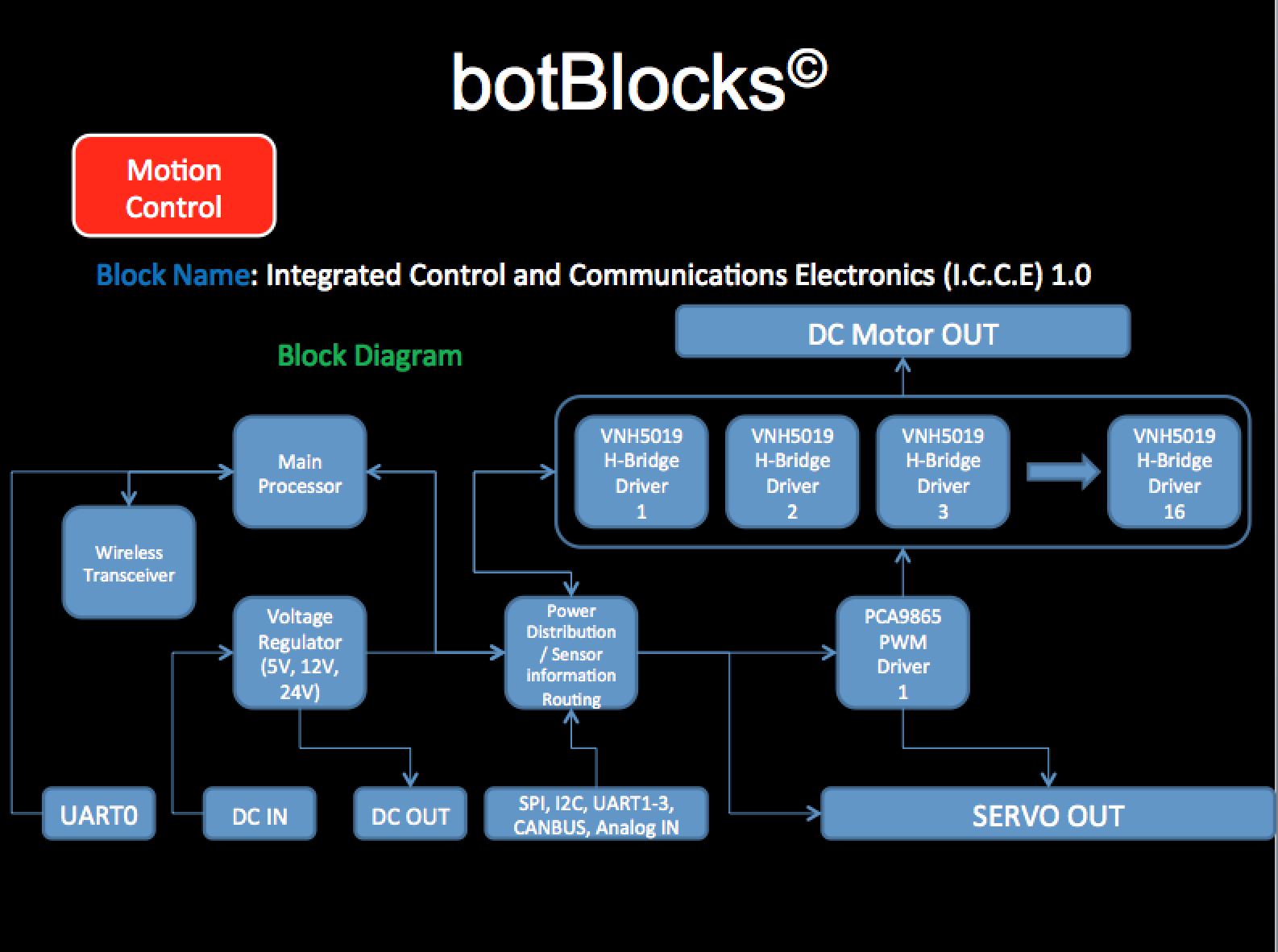
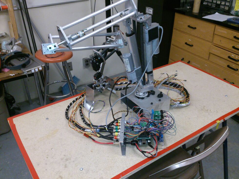
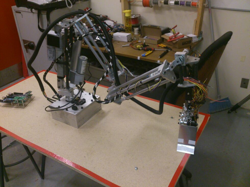
Our robotic arm is different than any other arms in the sense that it has more flexibility due to more number of links. The total length of the arm is 1.3 meter!. Most robotic arms are half of that and contains only two links (3 joints). Our arm offers 6 DOF and uses AX-18 servos for better performance. The flows diagram of the ICCE system (Motion control) is shown below:
Images ( Setup/Schematics/Results)
Latest Simulations & Results
Some of the latest results we have obtained are shown below:
Voice recognition with improved accuracy. We have increased the performance by a huge margin after making our own custom module. Now it recognizes with more accuracy and faster.
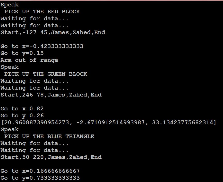
The figure below shows communication between two blocks (the vision module and the voice recognition module) and inverse kinematics calculation.
We can see that command are recognized in the voice recognition block (module). It then sends that data to the vision module, which locates the green block (the second command in the image) and finds its 2D position in the image. It then sends the position back to the voice recognition module in a frame. The frame starts with a 'Start' flag and ends with an 'End' flag. After the 'Start' flag it specifies the data slot followed by the source (which is James' block for vision, hence 'James'), then followed by the destination ( which is Zaheds block for voice recognition, hence 'Zahed'). We check if this packet is meant for us and then process it, otherwise discard it. With the coordinates we use inverse kinematics (implemented by Jookhun) and find the angles of the 3 joints, which is shown in the figure. These angles are then used to set the arm joints so that the target position is reached and the action executed.
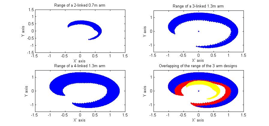
The figure below shows the solved kinematics model for a 1.3 meter, 2-linked, 3-linked, 4-linked arm respectively.
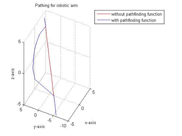
In the figure we can see the range of the arm (possible positions that it can reach) for different links. We can see that as we increase the number of links (hence joints) of the arms, the arm can reach more position, meaning it has more flexibility. A superimposed image of the three combinations is also shown on the fourth figure of the above figure. The figure below shows the two trajectories for the robotic arm with and without pathfinder algorithm. The pathfinding algorithm allows the robot to avoid obstruction in it's way by following a different route.
From the figure we can see that without the pathfinding algorithm, we have a straight path that the robot follows, which might result in a collision with obstacles that lie on that path. With the pathfinding algorithm we are able to detect those obstacles and thus avoid collision.
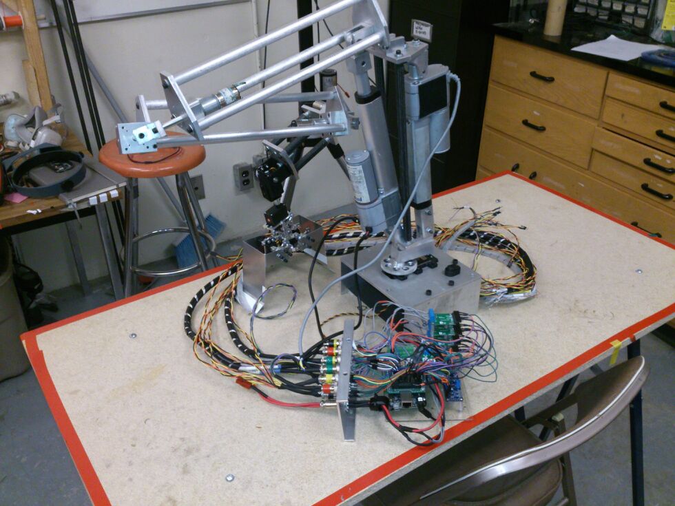
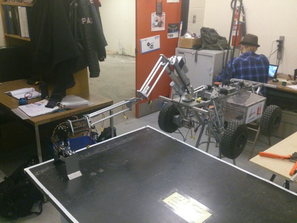
The figures below shows the design of our final robotic arm.
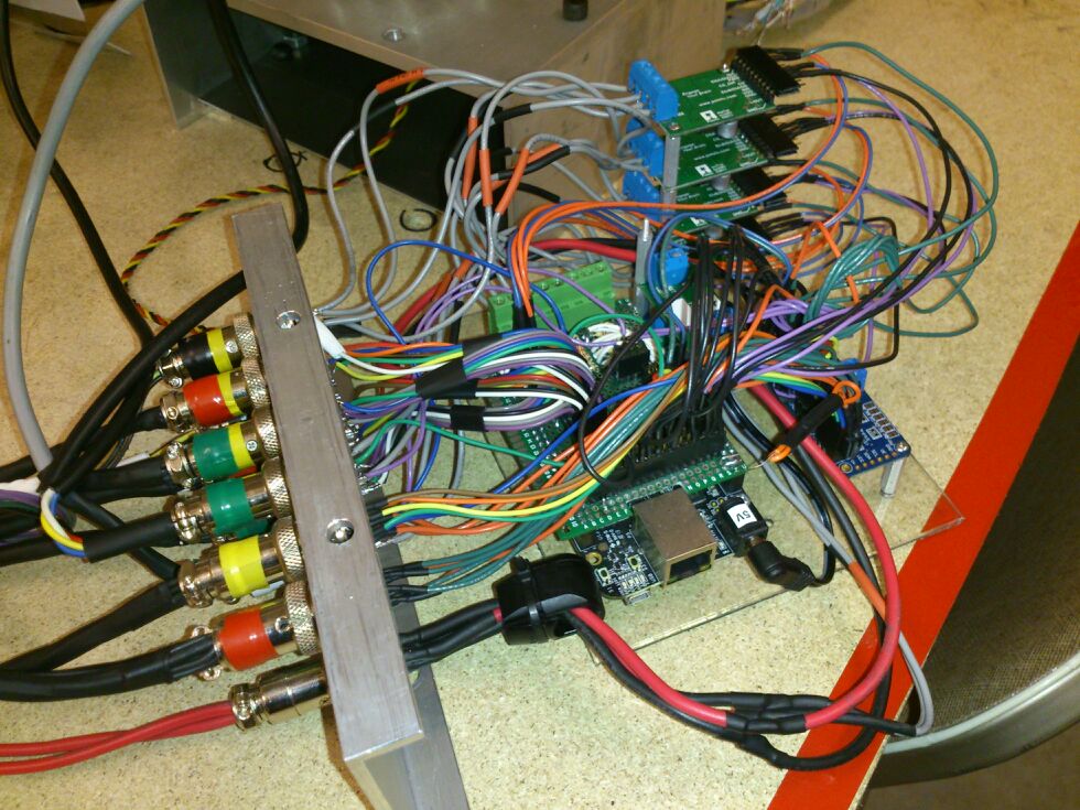
The figures above shows the internal communication hardware of the robotic arm, the length of the arm, the joints, and it also shows the arm integrated with a mobile platform. This shows the versatility of our design, that is, it can be used in many platforms whenever required.
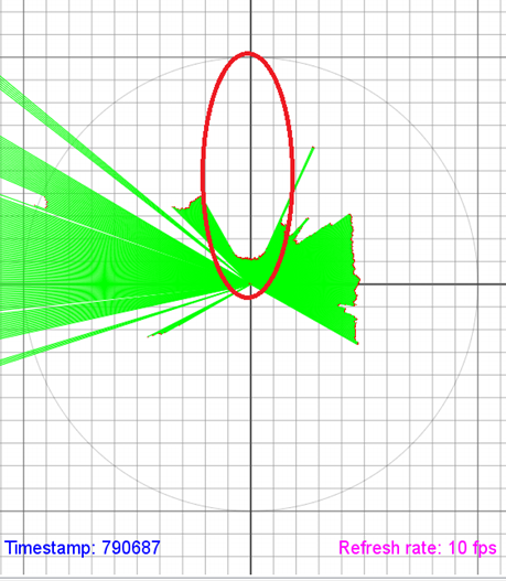
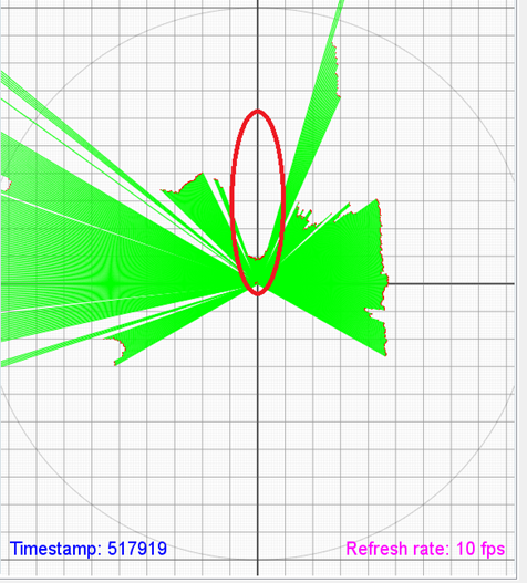
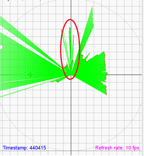
The figures below shows some results from sensor and mapping using the laser sensor. These figures demonstrates the problems of transparent objects when the laser scans the room. The transparent objects seems to give wrong information about their position because of scattering, reflection and diffraction.
We see this as a possible issue and the way we are going to handle this is by using opaque objects in the environment instead of transparent.
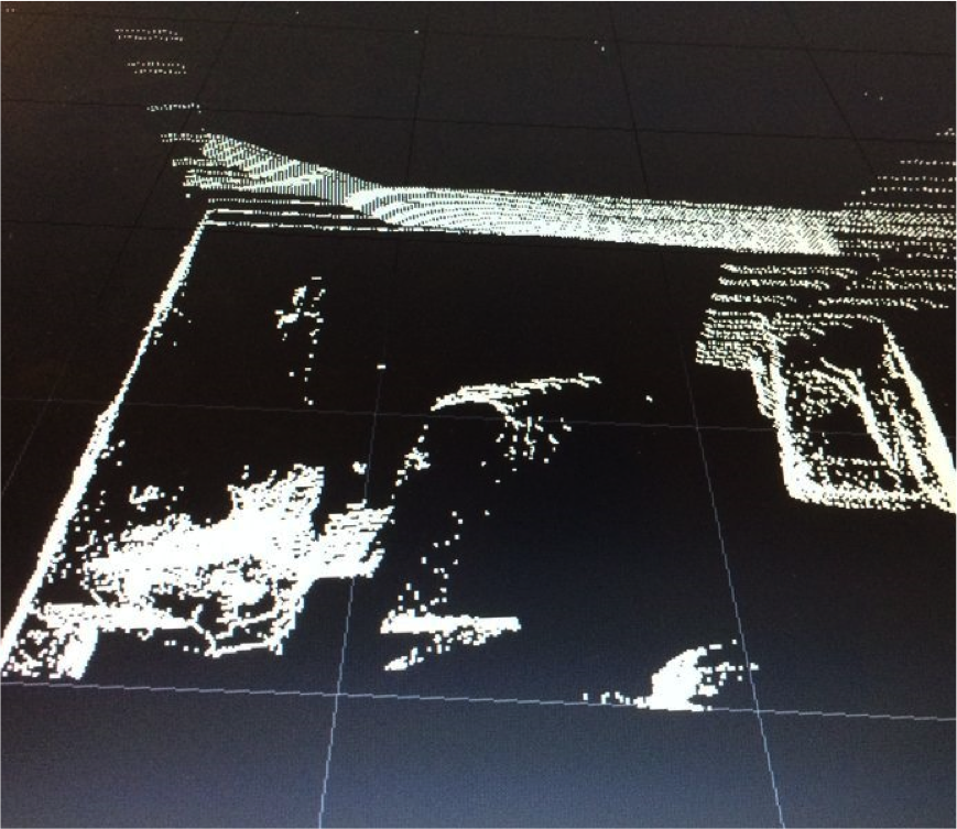
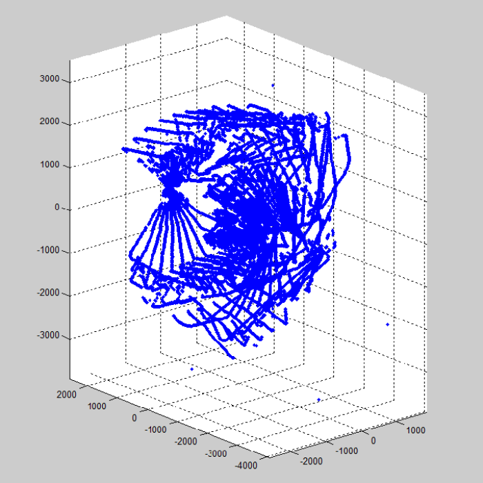
The figure below shows the point cloud that we were able to construct from the Hokuyo laser sensor. The image shows the 3D map of the room that was scanned and the objects. This point cloud is used in conjunction with the computer vision to get the coordinates of the target in order to interact with it.
Old Simulations & results
An application of our design is illustrated in the image below.
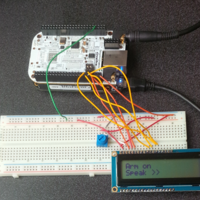
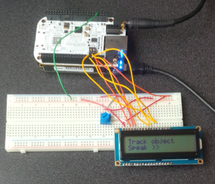
Voice recognition showing command detected on a screen
Plot of data points from Sensor, scan of a room
Potential Clients
Video Demo
The latest video of our project (5 min video) is shown below:
In case the above video doesn't work, here is the link to it:
Here is a video demo showing the arm tracking a blue object. Videos are not support by the dokuwiki (we tried), hence please download it to play. Sorry for the inconvenience.
Another video showing arm movement.
Funding
- Lassonde School of Engineering ( $1000),
- York University Robotic Society (YURS) (approximately $2500)
- Resources for building the arm
- Machinery for fabrication of the arm
- Sensors and other materials
Latest Presentation
- Presentation Nov. 15th, 2013
- Presentation January 8th, 9th, 2014

